- 您现在的位置:买卖IC网 > Sheet目录2006 > LTC2411-1IMS#TRPBF (Linear Technology)IC A/DCONV DIFF INPUT&REF 10MSOP
LTC2411/LTC2411-1
35
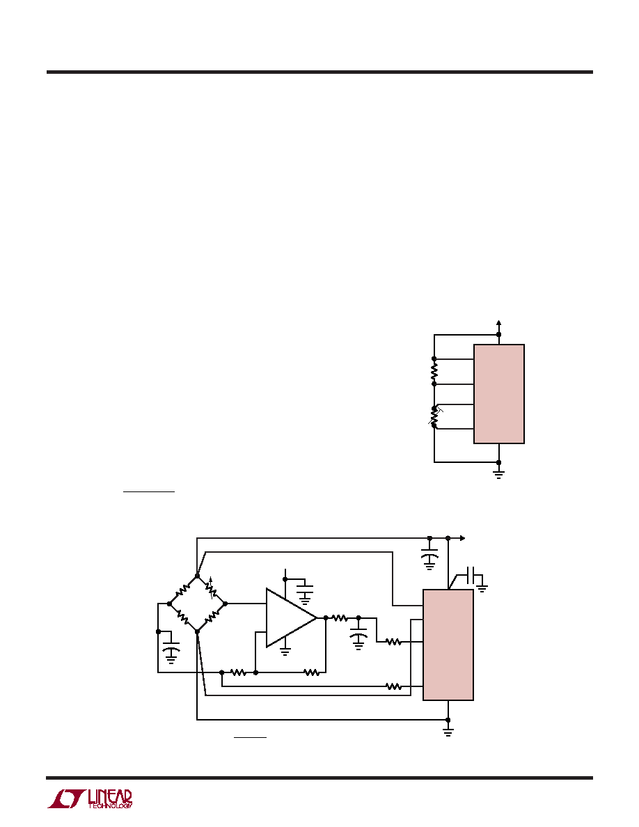
Figure 42. Bridge Amplification Using a Single Amplifier
APPLICATIO S I FOR ATIO
WU
UU
Note that this 4-amplifier topology has advantages over
the typical integrated 3-amplifier instrumentation ampli-
fier in that it does not have the high noise level common in
the output stage that usually dominates when an instru-
mentation amplifier is used at low gain. If this amplifier is
used at a gain of 10, the gain error is only 10ppm and input
referred noise is reduced to 0.15
VRMS. The buffer stages
can also be configured to provide gain of up to 50 with high
gain stability and linearity.
Figure 42 shows an example of a single amplifier used to
produce single-ended gain. This topology is best used in
applications where the gain setting resistor can be made
to match the temperature coefficient of the strain gauges.
If the bridge is composed of precision resistors, with only
one or two variable elements, the reference arm of the
bridge can be made to act in conjunction with the feedback
resistor to determine the gain. If the feedback resistor is
incorporated into the design of the load cell, using resis-
tors which match the temperature coefficient of the load-
cell elements, good results can be achieved without the
need for resistors with a high degree of absolute accuracy.
The common mode voltage in this case, is again a function
of the bridge output. Differential gain as used with a 350
bridge is:
A
RR
R
V ==
+
995
12
1 175
.
Common mode gain is half the differential gain. The
maximum differential signal that can be used is 1/4 VREF,
as opposed to 1/2 VREF in the 2-amplifier topology above.
Remote Half Bridge Interface
As opposed to full bridge applications, typical half bridge
applications must contend with nonlinearity in the bridge
output, as signal swing is often much greater. Applications
include RTD’s, thermistors and other resistive elements
that undergo significant changes over their span. For
single variable element bridges, the nonlinearity of the half
Figure 43. Remote Half Bridge Interface
0.1
F
5V
REF+
REF–
IN+
IN–
GND
VCC
2
3
2
4
6
7
3
350
BRIDGE
4
5
2411 F42
6
1
–
+
LTC1050S8
5V
0.1
V
R2
46.4k
20k
175
1
F
10
F
R1
4.99k
AV = 9.95 =
R1 + R2
R1 + 175
+
1
F
+
LTC2411/
LTC2411-1
2411 F43
REF–
IN+
IN–
GND
VCC
VS
2.7V TO 5.5V
2
3
4
5
PLATINUM
100
RTD
R1
25.5k
0.1%
6
1
4
3
2
1
REF+
LTC2411/
LTC2411-1
发布紧急采购,3分钟左右您将得到回复。
相关PDF资料
LTC2418IGN#TRPBF
IC ADC 24BIT DIFF INPUT 28SSOP
LTC2431IMS#TRPBF
IC ADC 20BIT DIFFINPUT/REF10MSOP
LTC2433-1IMS#TRPBF
IC ADC DIFF 16BIT 3WIRE 10-MSOP
LTC2435CGN#TRPBF
IC ADC DIFF I/REF 20BIT 16-SSOP
LTC2442IG#PBF
IC ADC 24BIT 4CH 36-SSOP
LTC2446IUHF#TRPBF
IC ADC 24BIT 8CH HI SPEED 38QFN
LTC2448IUHF#TRPBF
IC ADC 24BIT HI SPEED 38QFN
LTC2451ITS8#TRPBF
IC ADC 16BIT DELTA SIG TSOT23-8
相关代理商/技术参数
LTC2411CMS
功能描述:IC A/D CONV 24BIT MICRPWR 10MSOP RoHS:否 类别:集成电路 (IC) >> 数据采集 - 模数转换器 系列:- 标准包装:1,000 系列:- 位数:16 采样率(每秒):45k 数据接口:串行 转换器数目:2 功率耗散(最大):315mW 电压电源:模拟和数字 工作温度:0°C ~ 70°C 安装类型:表面贴装 封装/外壳:28-SOIC(0.295",7.50mm 宽) 供应商设备封装:28-SOIC W 包装:带卷 (TR) 输入数目和类型:2 个单端,单极
LTC2411CMS#PBF
功能描述:IC A/D CONV 24BIT MICRPWR 10MSOP RoHS:是 类别:集成电路 (IC) >> 数据采集 - 模数转换器 系列:- 标准包装:1 系列:microPOWER™ 位数:8 采样率(每秒):1M 数据接口:串行,SPI? 转换器数目:1 功率耗散(最大):- 电压电源:模拟和数字 工作温度:-40°C ~ 125°C 安装类型:表面贴装 封装/外壳:24-VFQFN 裸露焊盘 供应商设备封装:24-VQFN 裸露焊盘(4x4) 包装:Digi-Reel® 输入数目和类型:8 个单端,单极 产品目录页面:892 (CN2011-ZH PDF) 其它名称:296-25851-6
LTC2411CMS#TR
功能描述:IC A/D CONV 24BIT MICRPWR 10MSOP RoHS:否 类别:集成电路 (IC) >> 数据采集 - 模数转换器 系列:- 标准包装:1,000 系列:- 位数:16 采样率(每秒):45k 数据接口:串行 转换器数目:2 功率耗散(最大):315mW 电压电源:模拟和数字 工作温度:0°C ~ 70°C 安装类型:表面贴装 封装/外壳:28-SOIC(0.295",7.50mm 宽) 供应商设备封装:28-SOIC W 包装:带卷 (TR) 输入数目和类型:2 个单端,单极
LTC2411CMS#TRPBF
功能描述:IC A/D CONV 24BIT MICRPWR 10MSOP RoHS:是 类别:集成电路 (IC) >> 数据采集 - 模数转换器 系列:- 标准包装:1,000 系列:- 位数:16 采样率(每秒):45k 数据接口:串行 转换器数目:2 功率耗散(最大):315mW 电压电源:模拟和数字 工作温度:0°C ~ 70°C 安装类型:表面贴装 封装/外壳:28-SOIC(0.295",7.50mm 宽) 供应商设备封装:28-SOIC W 包装:带卷 (TR) 输入数目和类型:2 个单端,单极
LTC2411IMS
功能描述:IC A/D CONV 24BIT MICRPWR 10MSOP RoHS:否 类别:集成电路 (IC) >> 数据采集 - 模数转换器 系列:- 标准包装:1,000 系列:- 位数:16 采样率(每秒):45k 数据接口:串行 转换器数目:2 功率耗散(最大):315mW 电压电源:模拟和数字 工作温度:0°C ~ 70°C 安装类型:表面贴装 封装/外壳:28-SOIC(0.295",7.50mm 宽) 供应商设备封装:28-SOIC W 包装:带卷 (TR) 输入数目和类型:2 个单端,单极
LTC2411IMS#PBF
功能描述:IC A/D CONV 24BIT MICRPWR 10MSOP RoHS:是 类别:集成电路 (IC) >> 数据采集 - 模数转换器 系列:- 标准包装:1 系列:microPOWER™ 位数:8 采样率(每秒):1M 数据接口:串行,SPI? 转换器数目:1 功率耗散(最大):- 电压电源:模拟和数字 工作温度:-40°C ~ 125°C 安装类型:表面贴装 封装/外壳:24-VFQFN 裸露焊盘 供应商设备封装:24-VQFN 裸露焊盘(4x4) 包装:Digi-Reel® 输入数目和类型:8 个单端,单极 产品目录页面:892 (CN2011-ZH PDF) 其它名称:296-25851-6
LTC2411IMS#TR
功能描述:IC A/D CONV 24BIT MICRPWR 10MSOP RoHS:否 类别:集成电路 (IC) >> 数据采集 - 模数转换器 系列:- 标准包装:1,000 系列:- 位数:16 采样率(每秒):45k 数据接口:串行 转换器数目:2 功率耗散(最大):315mW 电压电源:模拟和数字 工作温度:0°C ~ 70°C 安装类型:表面贴装 封装/外壳:28-SOIC(0.295",7.50mm 宽) 供应商设备封装:28-SOIC W 包装:带卷 (TR) 输入数目和类型:2 个单端,单极
LTC2411IMS#TRPBF
功能描述:IC A/D CONV 24BIT MICRPWR 10MSOP RoHS:是 类别:集成电路 (IC) >> 数据采集 - 模数转换器 系列:- 标准包装:1,000 系列:- 位数:16 采样率(每秒):45k 数据接口:串行 转换器数目:2 功率耗散(最大):315mW 电压电源:模拟和数字 工作温度:0°C ~ 70°C 安装类型:表面贴装 封装/外壳:28-SOIC(0.295",7.50mm 宽) 供应商设备封装:28-SOIC W 包装:带卷 (TR) 输入数目和类型:2 个单端,单极